Free Shipping $99+ | Duties Covered in Select Countries ✅ [Check Policy]
Sofle RGB MX Build Guide
Bill of materials
| Name | usage quantity | remark |
| SofleRGB-MX-PCB | 2 | |
| Reset switch | 2 | |
| TRRS jack | 2 | wired |
| Reset switch | 2 | |
| Diodes | 60 | |
| hotswap sockets for MX | 58 | |
| EC11 encoder | 2 | |
| RGB LEDs SK6812MINI-E | 72 | |
| ProMicro rp2040 | 2 | wired |
| ProMicro nrf52840 | 2 | wireless |
| OLED module | 2 | |
| 12P female header socket | 4 | |
| MUC single pin header | 48 | |
| 4P female header socket | 2 | |
| Screen single pin header | 8 | |
| USBLC6-2SC6 | 2 | wired |
| Resistor | 2 | wired |
| MX1.25 2P ultra-thin battery sockets | 2 | wireless |
| MX1.25 2P ultra-thin battery connectors | 2 | wireless |
| Power switch | 2 | wireless |
If you are making a wireless firmware keyboard, you can skip soldering the components noted as wired.
Tools and materials
- Soldering iron: It is recommended to use a soldering iron with adjustable temperature.
- Solder wire: It is recommended to use solder wire with a tin content of more than 60%.
- Solder paste (not necessary). With solder paste, it is easier to solder LEDs and diodes.
- Tweezers: Antistatic tweezers are preferred.
Warnings and disclaimers
If this is your first time soldering a split keyboard, it is recommended that you read this Build guide first before starting.
Think twice, solder once. Desoldering is frustrating and it’s easy to mess up things.
Be gentle with the USB on your microcontroller. They are easy to break.
Steps
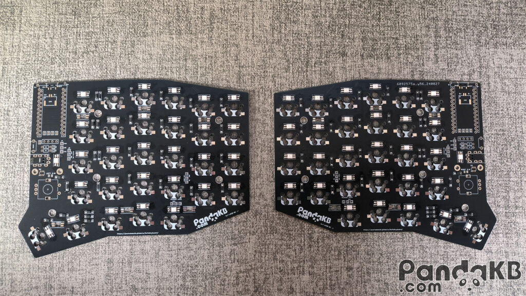
The PCB does not distinguish between left and right. That is to say, the PCB is universal for left and right. However, when you start soldering, you need to determine which one is left and which one is right. Avoid having the finished product be two left-handed keyboards or two right-handed keyboards.
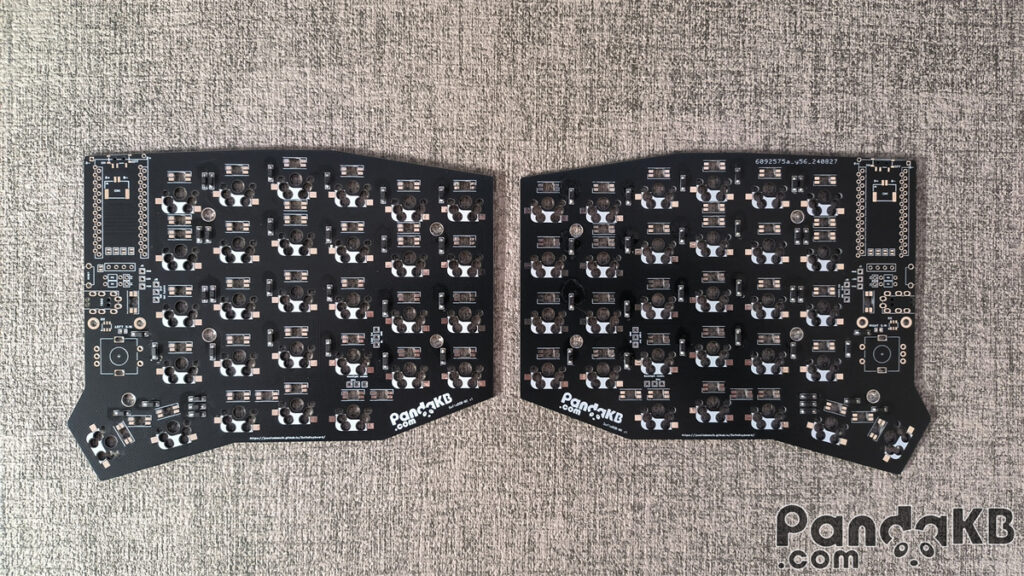
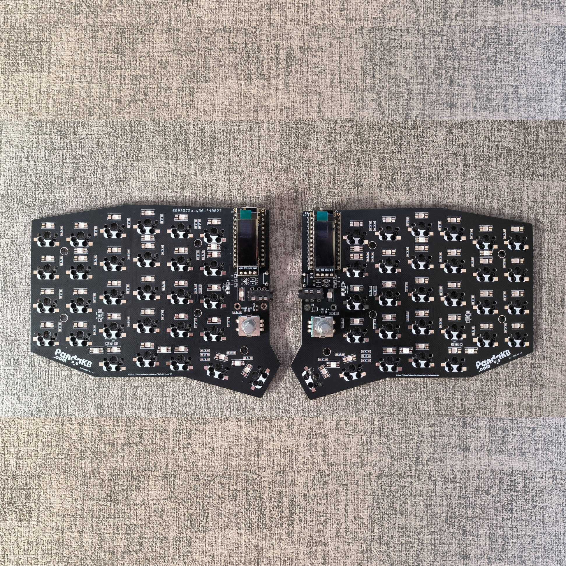
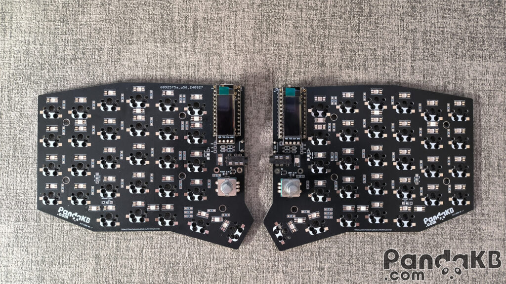
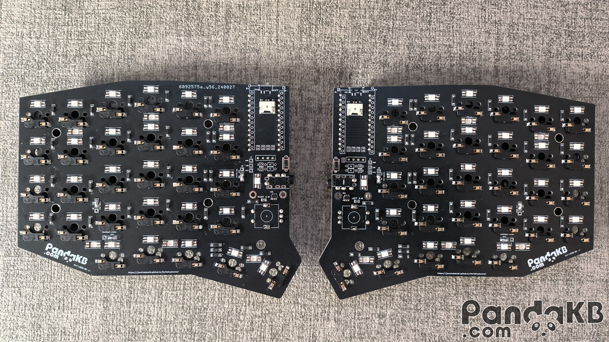
Welding finished product diagram
top surface
bottom surface
Diode welding
Diodes are polar, which means that direction is important. The stripe on the diode should match the silkscreen on the PCB, as shown below:
Rendering of the completed soldering of diodes.
LED welding (optional)
Welding LED is optional. If you don’t need LED, you can skip it.
There are 72 LEDs, of which 12 are underglow RGB LEDs and 60 are per-key RGB LEDs.
The light-emitting surface of the per-key RGB LEDs is facing the keycap, and that of the underglow RGB LEDs is facing the bottom. The soldering direction of the lights is as shown in the following figure. Align the notch angle of the LED with the marked angle on the PCB.
This is the rendering of the completed soldering of the per-key RGB LEDs.
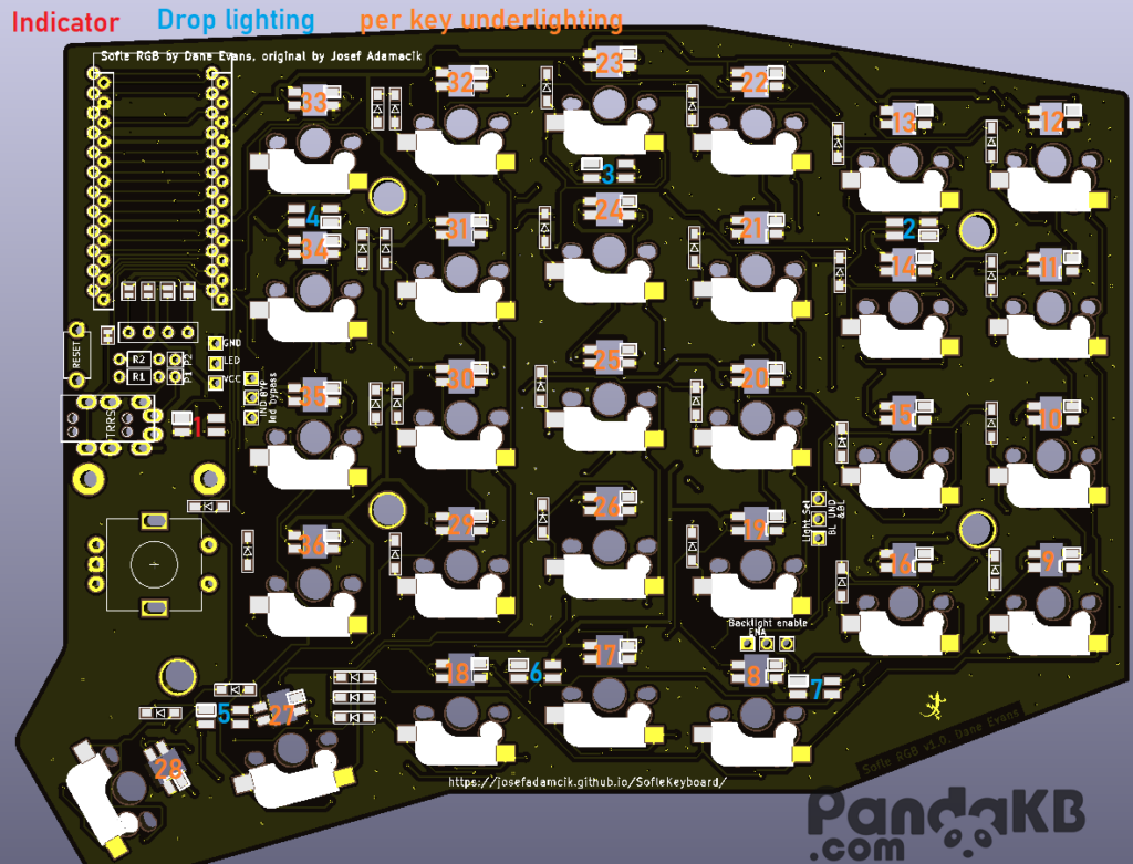
This is the rendering of the completed soldering of the underglow RGB LEDs.The position of the underglow RGB LEDs is shown in the picture below.
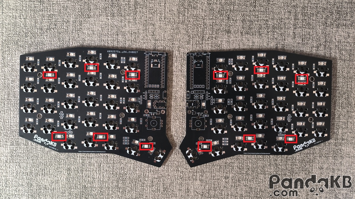
In order to achieve a flexible combination of per-key RGB LEDs, underglow RGB LEDs, and light strips, short-circuiting is required for the application of lights. If you want to turn on the per-key RGB LEDs, underglow RGB LEDs, and light strips, you can refer to the short-circuiting diagram below.
Soldering of Switch Sockets

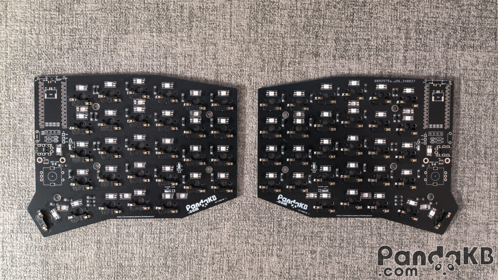
This is the rendering of the completed soldering of the Switch Sockets.
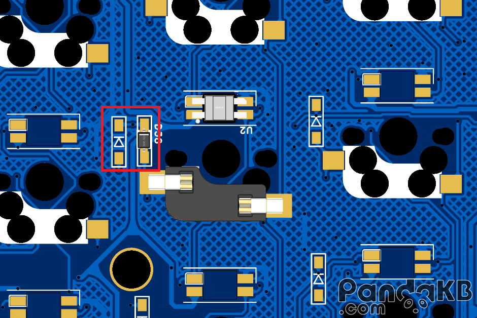
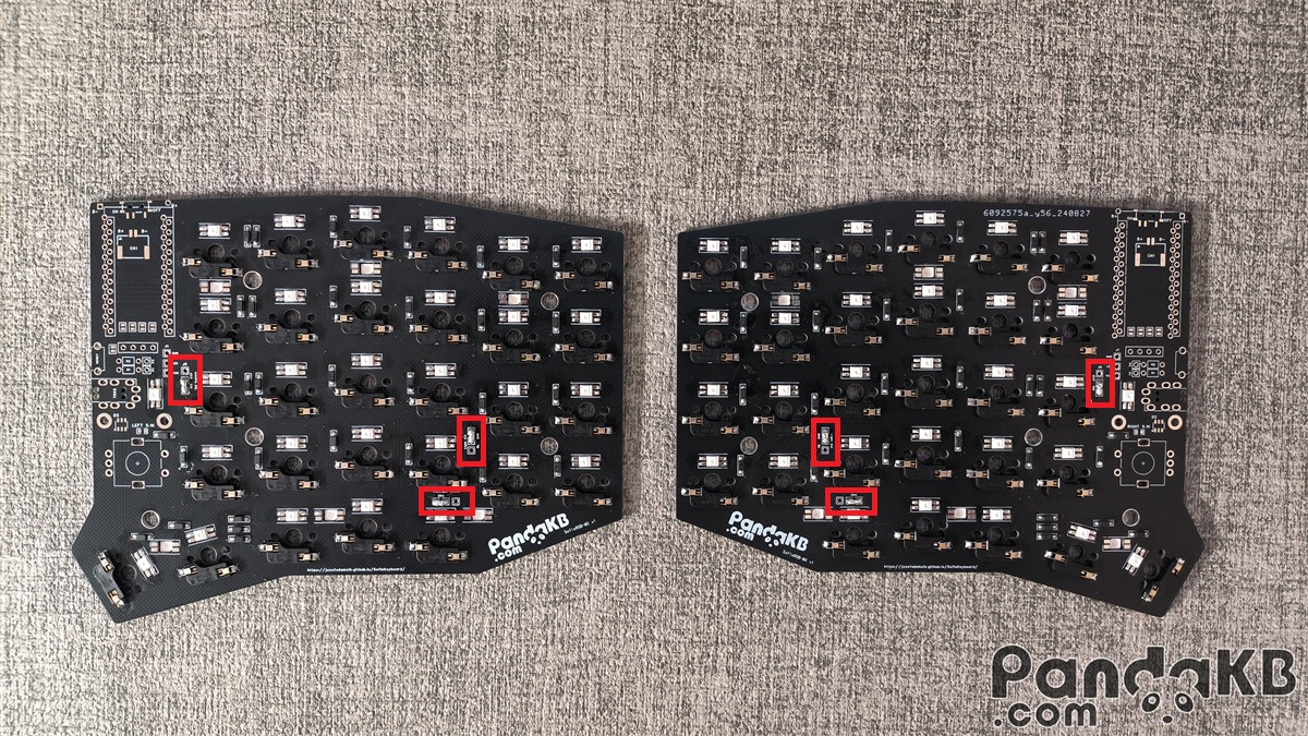
Soldering of USBLC6-2SC6 and Resistance (optional).
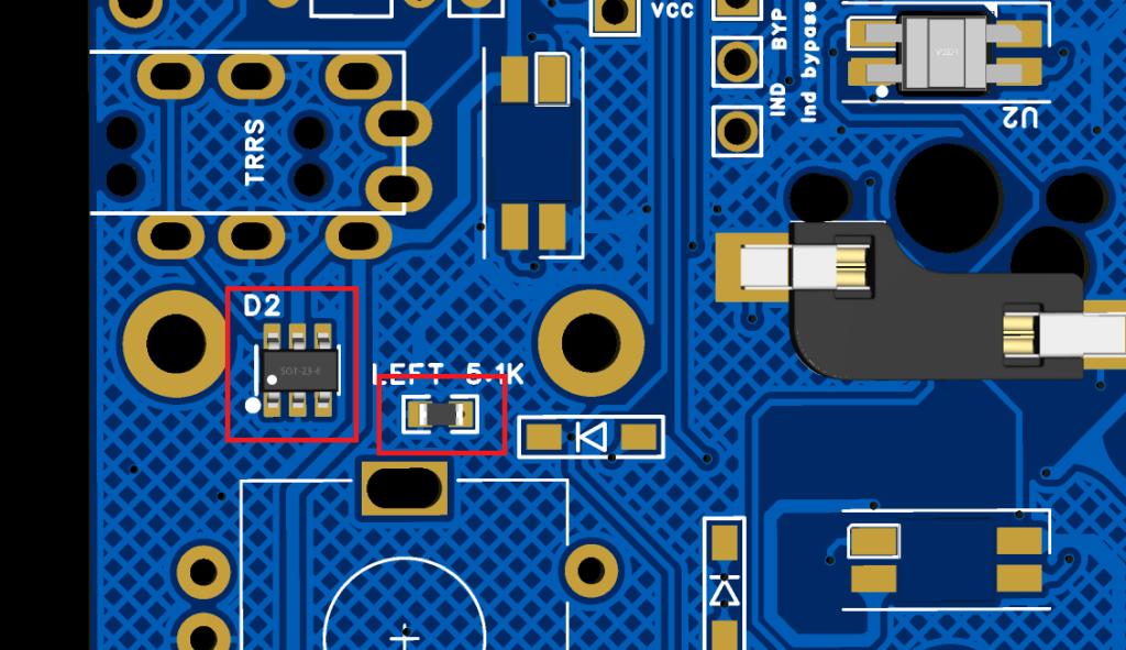
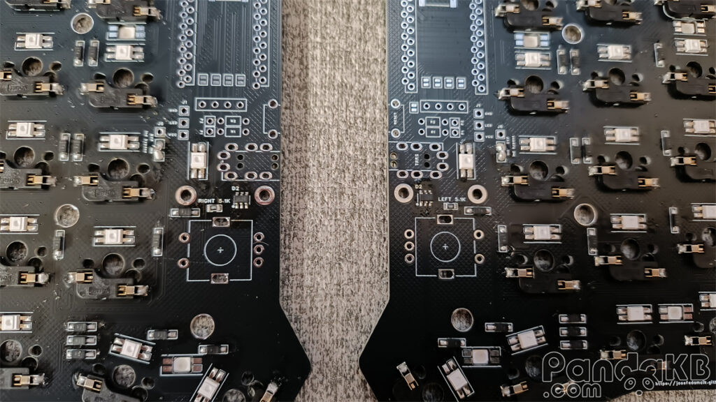
Soldering USBLC6-2SC6 and Resistance. These two are upgrade contents for QMK wired firmware keyboards. USBLC6-2SC6 can prevent the main control from being burned due to hot plugging of TTRS. Resistance can realize distinguishing between left and right hands. You can choose not to solder them. If you make a wireless firmware keyboard, you don’t need to solder these two components. The soldering direction of USBLC6-2SC6 is as shown in the following figure. The small dots on the component silk screen are in the same direction as the small dots on the PCB. Resistance has no direction. Both of these components are soldered on the bottom side, that is, on the same side as Switch Sockets are soldered.
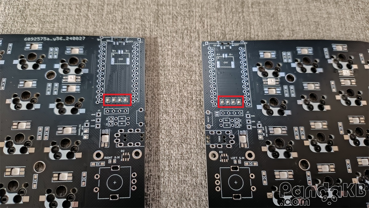
OLED Screen Jumper Welding
If you want to use the OLED screen, short-circuit the four places in the following figure. Short-circuit on the top surface of the PCB.
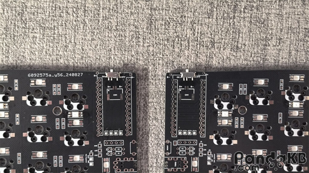
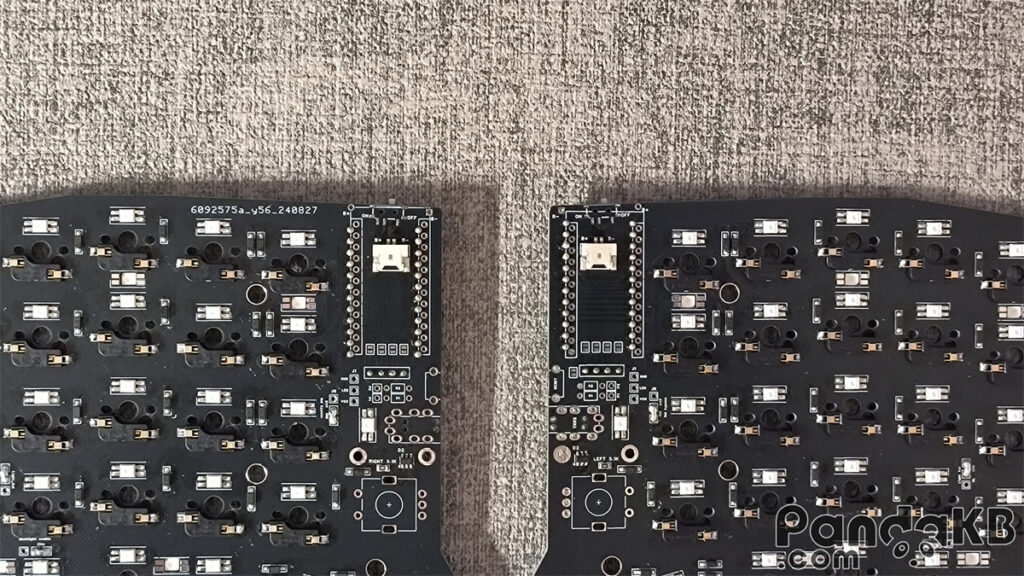
Power switch soldering
As shown in the following figure. It is recommended to solder on the top surface of the PCB. In this way, the switch is just below the Type-C port of the MCU, saving more space.
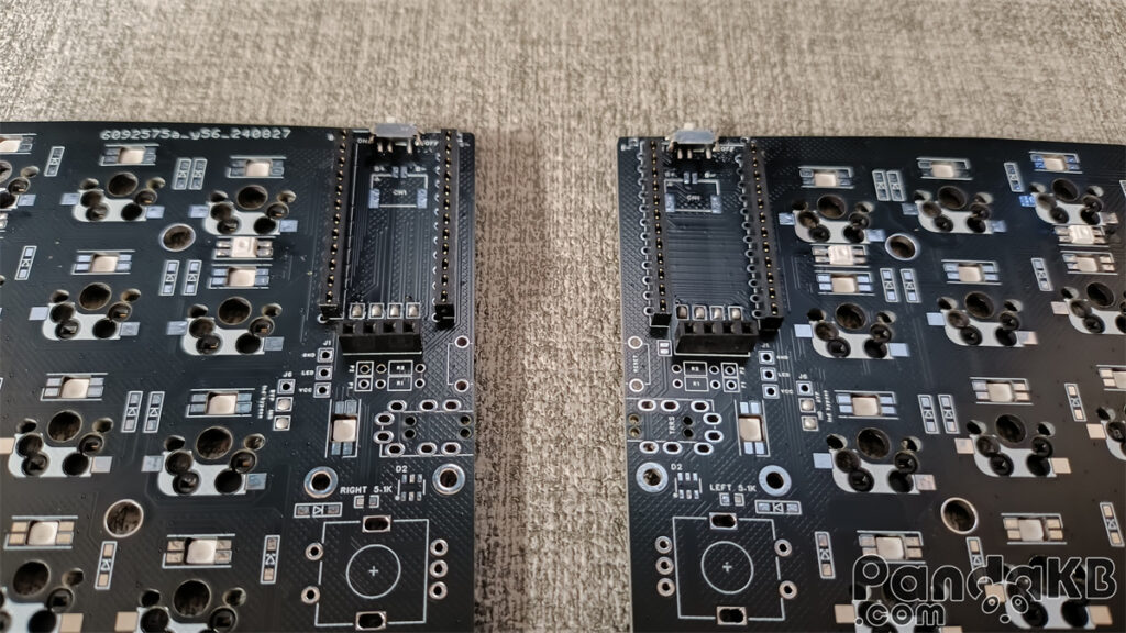
Solder the female header socket.
Solder the female header socket of the MCU and the female header socket of the screen.
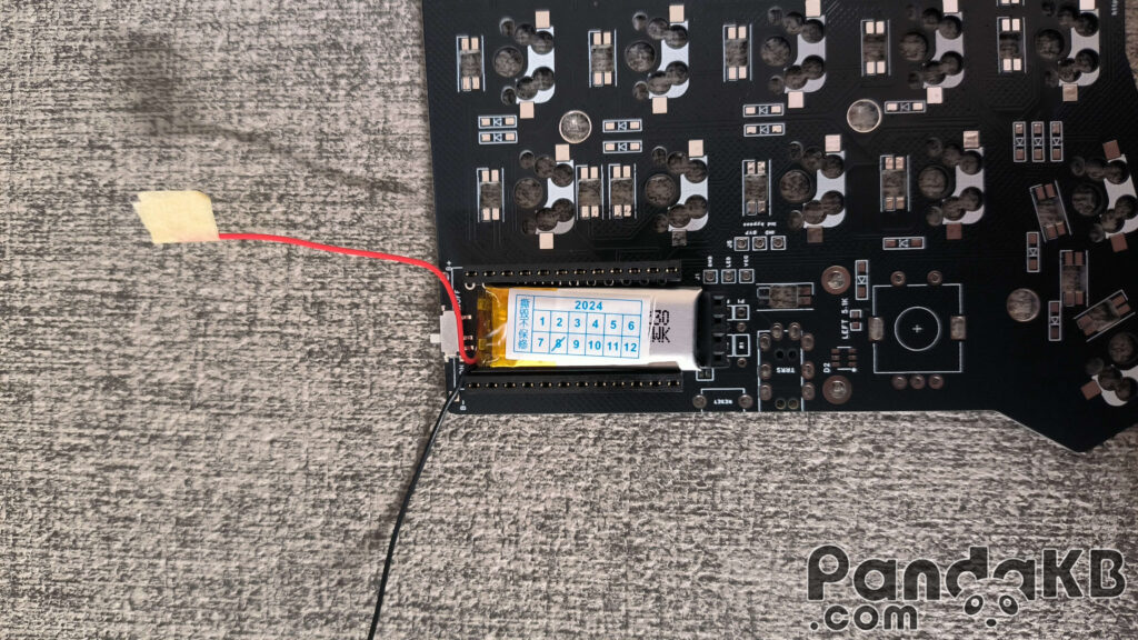
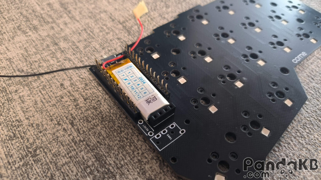
If using wireless, a battery is required. There are two battery interfaces. One is through the ultra-thin MX1.25 interface, which will be introduced later. The other is as shown in the picture below. For a small battery, you can place the battery under the main control. Place the battery and solder the red wire of the battery to the B+ welding hole above, and solder the black wire of the battery to the B- welding hole above.
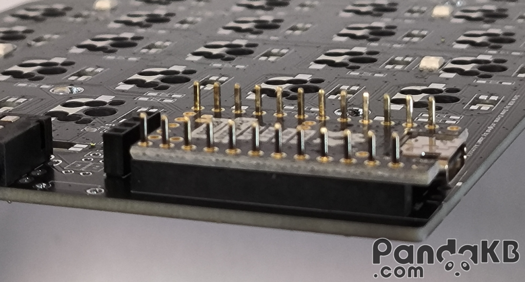
Insert a single pin header into the female header.(Here, a photo of Corne is borrowed.)
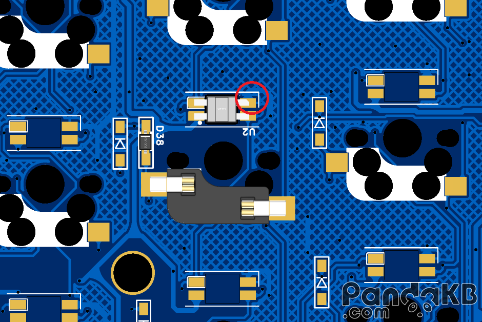
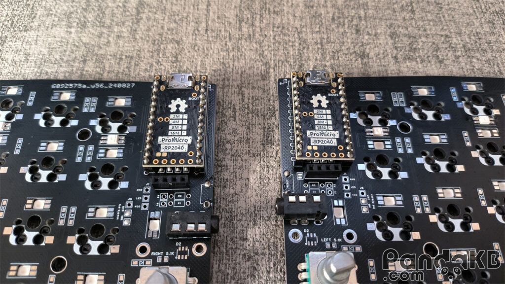
Solder the MCU
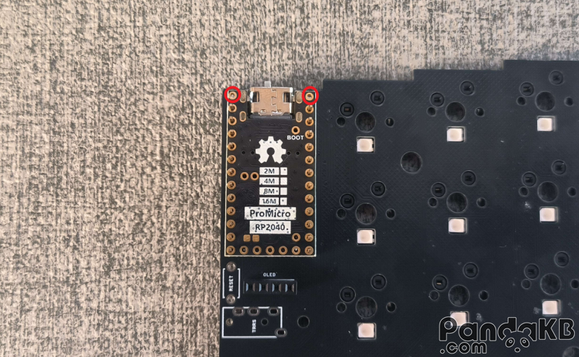
Place the MCU on the female header and let the pin pass through the welding holes of the MCU. The two welding holes above the MCU are left empty and not welded, as shown by the red circles in the following picture.
The following picture shows the situation where the battery of the wireless keyboard is placed under the MCU. Weld the MCU.After welding, use diagonal pliers to cut short the protruding pins.
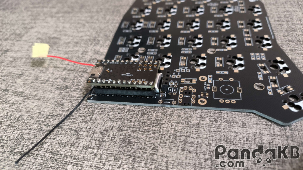
The following picture is a wired keyboard that does not require a battery. Weld the MCU.After welding, use diagonal pliers to cut short the protruding pins.
Weld the battery sockets (optional)
If you make a wireless keyboard and place the battery at the bottom of the PCB, you can refer to this step and weld the battery sockets.
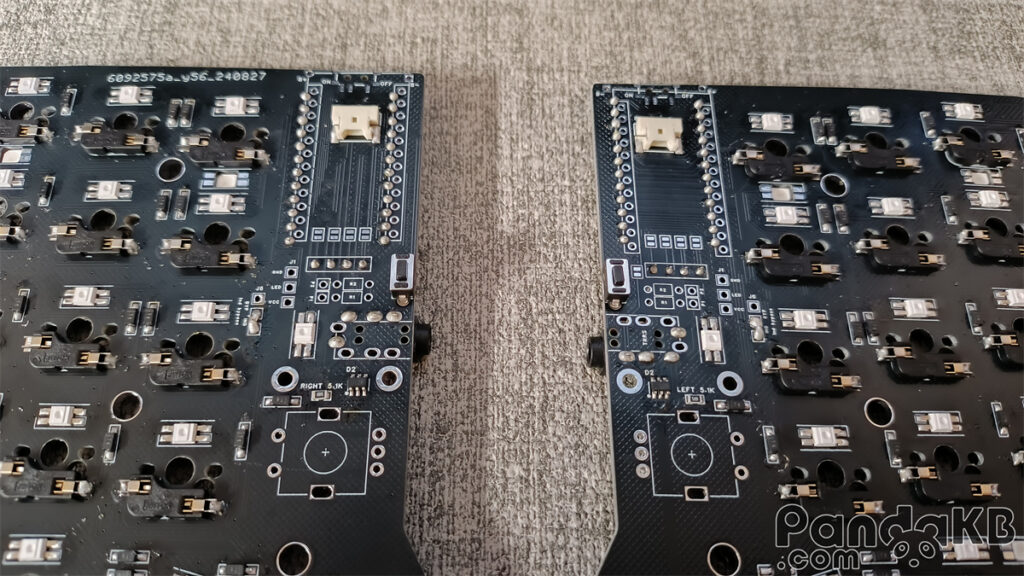
Weld the reset switch
The reset switch does not need to distinguish directions. However, note that according to the situation of the shell, choose to weld it on the top or bottom surface of the PCB. Usually, it is welded on the top surface of the PCB. There are also cases where there is a reset switch opening at the bottom of the shell. In this case, it can be welded on the bottom surface of the PCB. The following picture is a photo of welding on the bottom surface of the PCB.
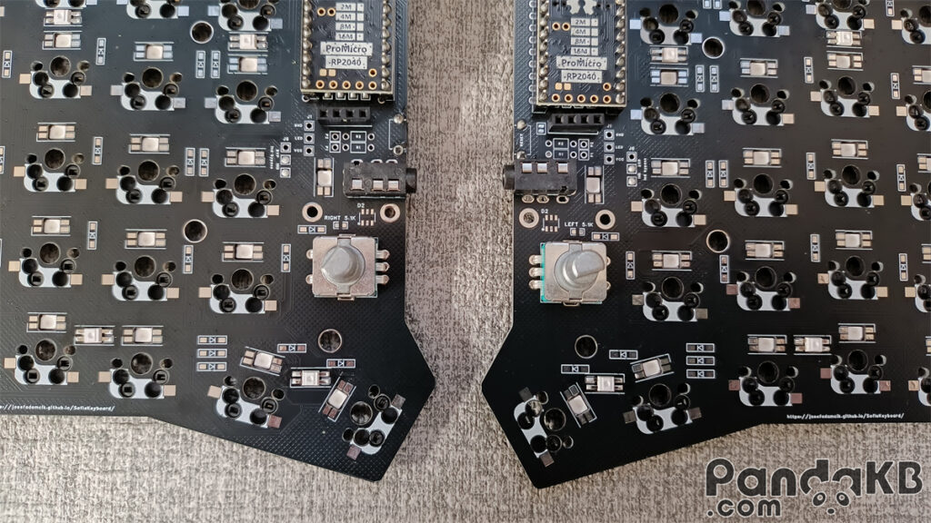
Weld the TRRS jack (wired) and EC11 encoder.
If making a wireless keyboard, there is no need to weld the TRRS jack.
Weld the screen.
Insert pins at the female header of the screen, place the screen, and weld.
Common Issues
Incorrect RGB Display
Check if the LED welding direction is correct; check if there are any faulty soldering joints on the LEDs.
Related products

Sofle RGB MX PCB Kit
Price range: $12.00 through $55.00
Sofle is 6×4+5 keys column-staggered split keyboard with encoder support. Based on Lily58, Corne and Helix keyboards.